


In engineering analysis, stress analysis covers the determination of the internal distribution of internal forces in solid objects for a given state of stress. It is often necessary to calculate principal stresses and the maximum shear stress for validation and judgement. Also, design and analysis of mechanical parts may require obtaining normal and shear stresses in different orientations at a certain location. Principal stresses (in 2D or 3D) and stress transformations can be obtained conveniently by using Mohr's Circle Stress Analysis Tool.

To draw Mohr Circle, we plot a line between 2 specific points (σ22, τ21) and (σ11, τ12) which will become diameter of Mohr’s Circle. Most used sign conventions in engineering and geomechanics for rotations and specific point locations are as follows:
Sign Conventions:
Sign Convention 2 (SC2):
Positive Shear would cause a counter-clockwise rotation of the infinitesimal element about the element center.
Therefore τ12 is plotted positive on Mohr’s Circle and τ21 is plotted negative.
Positive rotations are clockwise
Sign Convention 1 (SC1):
Positive Shear would cause a clockwise rotation of the infinitesimal element about the element center.
Therefore τ21 is plotted positive on Mohr’s Circle and τ12 is plotted negative.
Positive rotations are counter-clockwise.


Transformations (SC1):
Mohr’s circle is a two-dimensional graphical representation of the transformation law for the Cauchy stress tensor.
For a stress state which is rotated by θ (45˚ in example), shear and normal stresses are calculated with the transformation equations given below.


With the following substitutions, transformation equations turn out to Mohr’s Circle equations.

Same transformation can be graphically illustrated easily with 2θ transformation (90˚) on Mohr's Circle representation. Red zone on circle boundary represents 2θ rotation from original location.


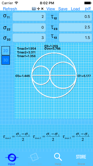
3D Mohr’s Circle Presentation:
3D Stresses, so called spatial stress problem, are given by six stress components (figure).
3 principal stresses, which are the eigen values of the three by three symmetric matrix and the three maximum shear stresses can be also illustrated with the Mohr’s Circles presentation.
For more suggestions, bugs&problems:
